2D vs 3D floor plans: which view answers your question?
Use 2D plans for boundaries and dimensions, and 3D views for height and room relationships. See how to review the same layout in both.
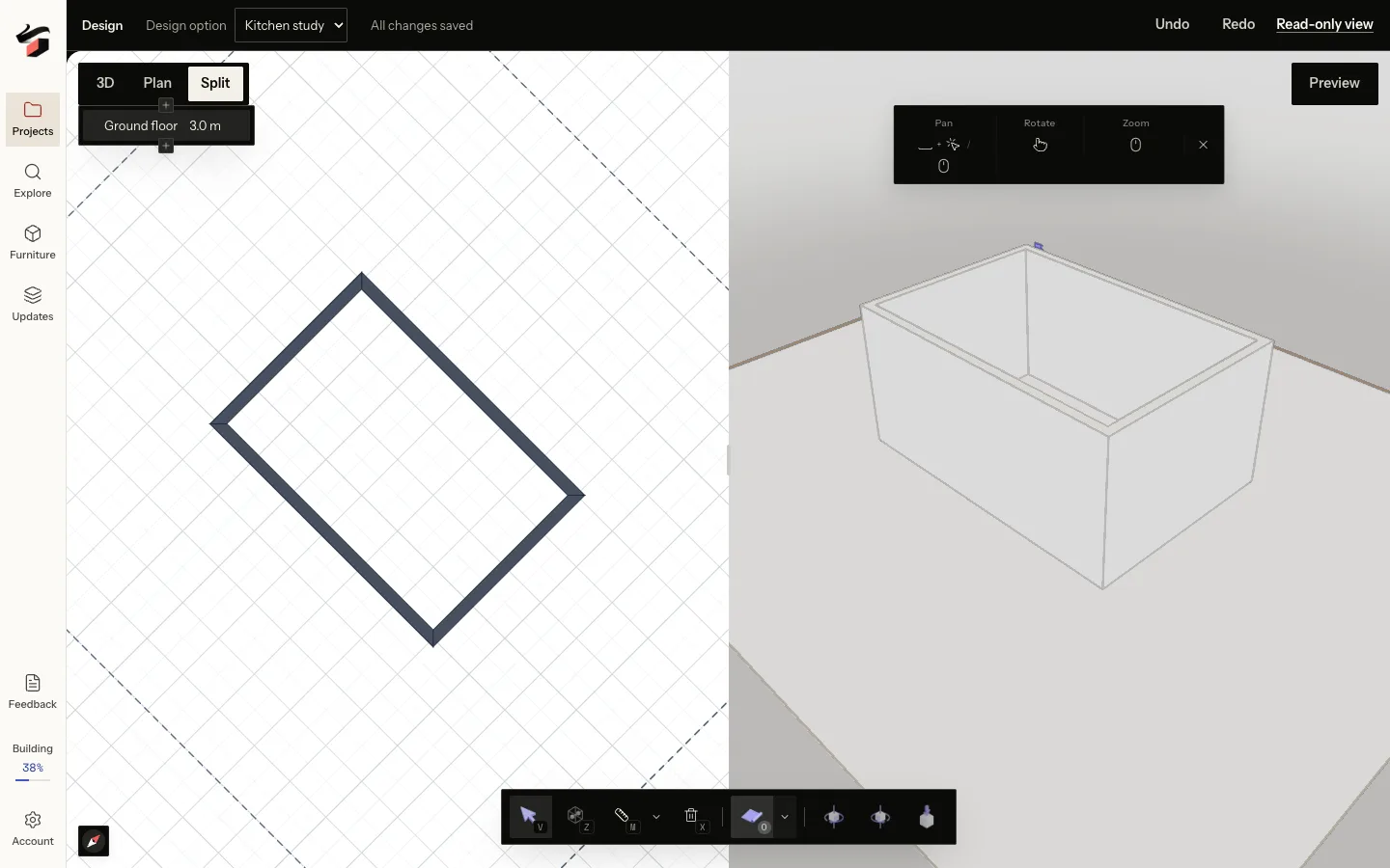
Use a 2D floor plan to trace room boundaries, compare dimensions and inspect furniture footprints. Use a 3D model to examine height, sightlines and how the room feels from a particular position. For a purchase or renovation decision, the useful workflow moves between them. Each view makes some questions easier to answer and leaves others out.
What a 2D floor plan explains well
A plan gives you a consistent view from above. It makes the connection between rooms easy to trace and lets you compare distances without perspective making the far end of the room look smaller. Door swings, window positions, dimensions and room labels can carry information that is difficult to read in a furnished 3D view.
For a bedroom, start in plan with the outside dimensions of the bed frame and the door and wardrobe positions. Follow the access route to both sides of the bed. Check what the dimension lines actually measure: inside faces, outside faces or another reference. A decorative brochure plan without usable dimensions cannot settle the same questions as a dimensioned drawing.
What a 3D floor plan adds
The 3D view helps connect the plan to a room you can picture. Look from the entrance to understand the first view into the space. Look from a chair to see how a tall cabinet relates to a window. Rotate an overview to understand adjacent rooms, then inspect the vertical relationships between doors, walls, ceilings and furniture.
Choose the camera for the question. A wide overhead view explains the whole apartment. An eye-level view explains the route into the living room. A close view can expose a surface junction, but it can also hide the circulation problem behind the camera. Keep enough context for a reviewer to locate the view in the plan.
Choose the view by the decision
| Question | Start with | Then check |
|---|---|---|
| Will the furniture fit? | A dimensioned plan and actual product sizes. | The 3D arrangement, moving parts and measurements in the room. |
| How do the rooms connect? | An overall plan showing every doorway. | An eye-level route through the model. |
| Does a tall object block an opening? | The object and opening locations in plan. | Heights and relationships in 3D. |
| Which material direction do we prefer? | Matching 3D views of the alternatives. | Surface boundaries in the model and physical samples. |
| What should a contractor build? | Appropriate verified project documentation. | The model as supporting context, with unresolved information identified. |
Keep a model separate from an image of it
A 3D model contains geometry you can inspect from different angles. An exported image records one view. A generated photoreal image interprets that view and may alter details. These outputs can work together, but sending a picture does not give the recipient editable geometry or a reliable way to measure another part of the room.
When sharing an image, include the plan or a small locator view if orientation is unclear. If the recipient needs to explore the space, agree on a supported model format or an appropriate project view. Explain whether the image is a direct model capture or a generated material proposal.
Review Plan and 3D together in Pascal
NoteIntegration preview · September 14, 2026. The Pascal integration is under review and has not been released to production. The screenshots show local test projects. Features and availability may change before release.
The Pascal integration includes Plan, 3D and Split views inside the project editor. Split places the two representations beside each other, as shown in the synthetic kitchen study above. It helps connect a selected wall or room in plan with its position in the model. The source drawing remains a separate reference for checking whether the reconstruction is correct.
Try this sequence: trace the entry route in Plan, inspect it at eye level in 3D, then return to Plan to review the narrowest point. If the views seem inconsistent, check camera visibility, selected level and saved revision before assuming the geometry changed. Read checking an AI-generated floor plan for source verification and render vs model for choosing a client handoff.